

How to install monorail electric wire rope hoist ?
How to install monorail electric wire rope hoist ?
1.Installation and technical requirements about the electric wire rope hoist

Buffer devices at both ends of track or I-beam must be installed completely;
Adjust the I-beam support points according to the drawings;
The splicing of I-beam must be carried out according to the drawing, and the lower flange must be polished smooth without wheel jamming.
Before operate the hoist, carefully check whether the reducer of the lifting part of the electric hoist is filled with lubricating oil and whether the traveling mechanism is filled with lubricating grease. Ensure that there is no oil or rust proof oil on the tread of electric trolley.
Read the installation instruction manual carefully, carry out splicing installation according to the steps, and connect according to the electrical drawings. Check the power supply of lifting and operating mechanism.
Check whether the fixed end of the wire rope is tightened and whether the stopper is wedged firmly.
Check whether the control button wiring is correct, and the safety rope for fixing the button must be installed.
According to the regulations, the hook must be painted with yellow and Black Zebra paint, and the hook safety device is complete. There must be three pressing plates at each end of the wire rope and the drum, and the bolts must be tightened. The exhaust device is correctly assembled and the upper and lower limit switches are installed correctly.
According to the actual situation of the construction site, the electric hoist can be installed by crane or installed with pulley block by winch; during hoisting, the steel wire rope must be protected to prevent damage to the equipment, and the wire rope sling for hoisting shall be selected according to the weight of the equipment.
One important point: adjust the gasket to make the clearance between the inner side of traveling wheel flange of electric hoist and I-beam rail flange is 3-5mm
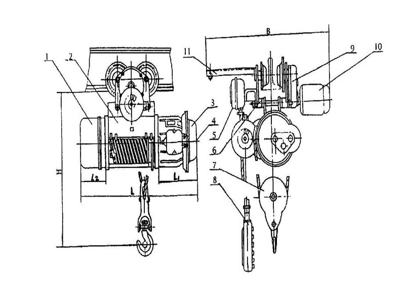
Remove the tail cover. Screw out the four screws that fix the adjusting nut, turn the adjusting nut clockwise to the limit position with a wrench, and then turn it anticlockwise for one turn to install the set screw.
By adjusting the two buffers on the limit rod, the fire limiter can be adjusted. The adjustment method is as follows: loosen the screw on the collision block, place the collision block on both sides of the guide rope clamp plate, and the splint pushes the collision block to move freely. Start the motor and start lifting. The chuck pushes the upper block to move. When the upper edge of the hook shell is 150 mm-50 mm away from the lower edge of the drum shell, stop lifting and click the lower button. Stop the machine when the rope guide moves back about 10 mm. Move the upper block near the chuck and tighten the screw. The adjustment of the lower limit position is the same as above, but the direction is opposite, but it must be ensured that when the hook is in the lowest position, the remaining wire rope on the drum is more than 3 turns.
2. Debugging:
After connecting the power supply, carry out no-load test: start the no-load positive and negative test run of each mechanism, and check whether the safety facilities work normally